How to design a retaining wall? | RCC Design
Main parts of Retaining Wall
The stem and base are the main parts of a cantilever type of retaining wall. The toe is the front portion and heel is the back portion. The stem is supported at the base and the wall tapers towards the top.
Wall Dimensions
Generally the height of the wall known and approximate dimensions are required to be assumed.
The length of the base is between 0.4 to 0.7 times the height of the wall. Toe to base ratio is 1:4. The thickness of the base slab shall be assumed to be little more than the thickness of the stem at the bottom. The minimum thickness of the stem shall be 200mm for construction purposes.

Earth pressure on wall
A length of one metre of the wall is considered for design.
Earth levelled up to the top of wall:
From Rankine’s theory of earth pressure
![]()
where,
P = total pressure on wall acting at H/3 from the base
H = total height in metres
W = weight or density of earth in kN/m3
Φ = angle of repose of earth
Stability of retaining wall
The assumed trial section of the wall shall be checked for stability. Stability check is required for (i) overturning and (ii) sliding. In both the cases the factor of safety shall not be less than 1.5.
1. Factor of safety for overturning
(Moment due to load of wall)/(Moment due to force P) ≥ 1.5
2. Factor of safety for sliding
(Total load of wall x μ)/Force P ≥ 1.5
where,
μ = coefficient of friction between base and the ground below.
Here is an example of the method of designing a cantilever wall.
An RC retaining wall 5 m high above foundation base has to retain earth with a horizontal surface at the top. The density of retained earth is 16 kN/m3 and angle of repose is 300. Design the cantilever wall and give approximate dimensions of heel, toe and base. Also check the stability of the wall. Use concrete M15 and steel Fe415 μ= 0.5.
Step One:
Design constants
Given:
Permissible stress in concrete, σcbc = 5 N/mm2
Modular ratio, m = 18.66,
σst = 230 N/mm2
x = 0.29d, z = 0.90d,
Mr = 0.65bd2, Pt = 0.32
Density of retained earth = 16 kN/m3
Angle of repose = 300
Trial Section
Height of the wall is 5 m.
Assume width of the base to be 0.6H
∴ Base = 0.6 x 5 = 3 m.
Assume toe to base ratio as 1: 4
∴ Toe = 3 x 1/4= 0.75 m.
Step Two
Bending moment and thickness of stem
Consider 1 m length of stem.
Horizontal pressure of earth on stem, (P)

Bending moment at the base of stem, i.e., 5 m below the top
M = P x H/3 = 67 x 5/3
= 111.66kN-m or 112 kN-m
The value of the bending moment goes on reducing towards the top and becomes zero at the top.
Bending moment at 2.5 m below the top,
 Step three
Thickness of stem (at the base)
Equating Mr to M,
Equating to
0.65bd2 = 112 x 106
0.65 x 1000 x d2 = 112 x 106
d = 415.09mm = 415mm
Assuming 20 mm Φ bars and 25 mm cover,
D = 415 + 20/2 + 25 = 450mm
Provide 20 mm thickness at the top
Thickness available at 2.5 m below the top
0.65 x 1000 x d2
d = 146.759mm = 147mm
Required thickness at 2.5 m below the top
 Step four
Calculating Steel
We have to calculate:
- Main steel
- Distribution steel
Calculating Main Steel
1. 5 m below the top,

Providing 20 mm Φbars, area of one bar is 314 mm2.
2.5 m below the top,

Minimum Steel = 0.12%

Hence taking Ast = 390mm2 and not 233.22mm2
Providing 12mmΦ bars, area of one bar 113mm2
Spacing = 1000 x 113/390 = 289.74mm = 290mm
Distribution Steel–0.12% of Ast

Providing 8 mm Φbars, area of one bar is 50.26 mm2.
Spacing = 1000 x 50.26/390 = 128.87mm = 125mm
Step Five
Check for shear
The formula for maximum shear at the base is given by,
V = 67kN
![]()
For concrete M15 and Pt = 0.31, Tc= 0.22 N/mm2
Since Tc > Tv, no shear reinforcement is required.
Step Six
The formula for Development length is given by,
(a) At the base of stem.
For 20 mm Φbars,
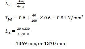
(b) At 2.5 m below the top,
For 12 mm Φbars;
Ld = 12 x 230/4 x 0.84 = 1369mm = 1370mm
Step Seven
Check for Stability
Assume thickness of base as 500mm
Total vertical loads
The calculation of vertical loads include weight of wall, weight of base and weight of soil.
Weight of wall

Weight of base
3 – 0.5 x 3 x 25 = 37.50kN
Weight of soil
4 – 1.8 x 5 x 16 = 144 kN
Total = Weight of wall + Weight of base + weight of soil
= 223.15kN = 223kN
Distance of total load Wr from toe point T

Factor of safety
1) For overturning
2) For sliding
